GIANT FOAMBOARD AIRCRAFT PROJECT

GFA Mk. I Manufacturing
The GFA Mk. I was a multi year project starting in the summer of 2019 to the maiden flight in the summer of 2022. The manufacturing of the aircraft took place on three build days. Two days were used to test assembilies and manufactuing methods this knowladge was then used to construct the entire aerostructure in a single day in the spring of 2022.
First Test Build: December 2019
First Steps
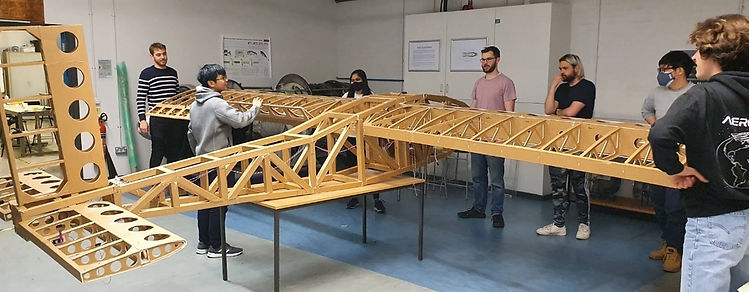
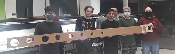
The very first build day was conducted when the project was in its infancy. Roughly a dozen students were involved. The students managed to construct a side of the fuselage. The purpose of this build day was to test manufacturing methods. Another build day was scheduled later in the year to make an attempt at building the entire aerostructure. This second build day was cancelled due to the 2020 global pandemic. Below can be seen several students with the product of the build day.
Second Test Build: 20-Dec-2022
A Huge Step in the Right Direction
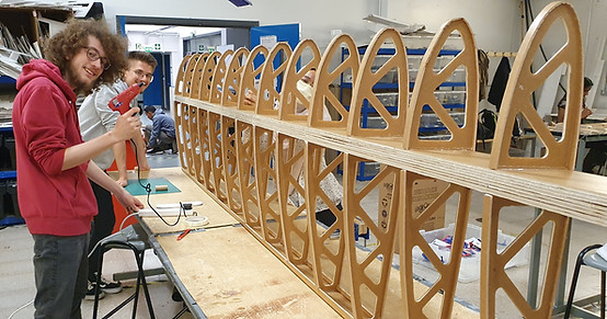
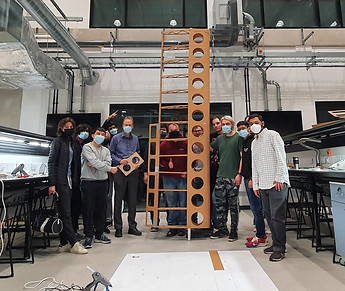
The manufacturing experiment took place on the 20/12/21 from 10am-4pm. Out of the 70 volunteers that signed up for the building activity, about 30-35 volunteer students participated in the build, with some arriving late or leaving early. This results in about 50% attendance.This build day had far higher expectations compared to the previous one. The expectations where justifled by the major improvement of lasercutting the parts before the build.
Aim
-
Test manufacturing methods and the difficulty of forming assemblies and subassemblies in support of the final build day, which is scheduled to happen 5-7 months later.
Objectives
-
Test training methods before manufacturing work begins
-
Assemble wing spar
-
Assemble one complete port or starboard main wing structure and control surfaces
-
Assemble complete fuselage Structure
All parts
The largest number of parts needed are the Perrin Tubes. But 7 other parts are required to assemble the complete wing section. These parts and their required numbers are listed below in Table 5. The table was used to predict the laser cutting time for each part including supporting activities such as loading, unloading, and processing the parts.
Objective evaluation
The day was considered to be a full success as lessons learned and promising progress was made.
-
Training session
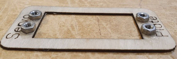
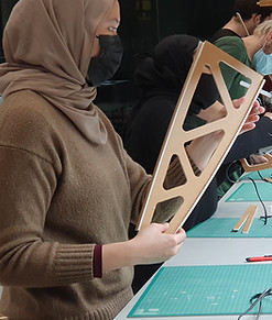
The training session started by separating the volunteers, taking about 10 of the most experienced to start work immediately on the main wing spar. The rest of the volunteers then underwent a 2-stage training session to better prepare them for the work ahead. The first stage of the training was creating several joints seen above. After stage 1 was completed, the volunteers moved on to constructing a practice Perrin tube and in teams of three. The practice template in Figure 17 shows what the workers had provided to them. The printed paper is full-size. The trainee will cut and glue the tubes together to match the template and the fuselage is assembled in the same fashion.
The training session was useful for helping the volunteers learn the skills required for manufacturing the aerostructures. The training session took about 1 ½ to 2 hours to complete. This was too much time spent practicing. When training finished lunch had started. With the day almost half over and most of the volunteers hadn’t manufactured anything for the build. For the next build day, it is recommended to reduce the training session or forgo it entirely.
The results of the training were shown at the end of the day with few parts being rejected due to human error. Less than the 15% predicted error for spare parts are needed for the next build if training is conducted in the same fashion.
-
Main Wing Spar Building
Work on main spar started immediately at beginning of the day. This is because the spar completion of the spar is critical for the subassembly of the main wing and the geometries, such as rib spacing, and alignment is based on the spar. The spar manufacturing method was similar to the fuselage by having a full-size printed template to build off of and taking the necessary measurements from the template.
This assembly contained no laser cut parts and required the volunteers to cut spar widths of foamboard from blank sheets. This width would then need to be glued together in the roughly 3.5m lengths. The 6-layer core of the spar would need to be crudely hacked out to remove some material and form the taper within the spar, tapering thinner as it went closer to the tip. Then the two outside layers would be combined to form the 8-layer thick spar.
This initial cutting, gluing, and layering proved to be a difficult task. Taking the team roughly 4 hours of nonstop work to complete. The amount of time taken was almost double what we expected. Significant alterations will need to be done to the design to ease manufacturing.
-
Main wing assembly
The main wing assembly started later in the day then planned, but progress was swift. The wing was fully assembled in about 2 hours, with its completion finishing manufacturing for the day.
The assembly of the wing started with the completion of the spar. The sub-assemblies of the wing include:
-
Spar
-
Ribs with strips
-
Leading Edge
-
Trailing edge
-
Flaps and ailerons
Work on these sub-assemblies happened after training with the workforce being split in half between wing assembly and fuselage manufacturing. All parts for the main wing, excluding the main spar had been laser cut beforehand. This meant that very little hand measuring, and cutting was required. Both the leading edge and trailing edge consisted of 6 pre-cut lengths that needed to be glued together and prepared to be bent around the ends. The ribs required a 15mm strip of foamboard to be glued to the edges to increase the surface area of the piece allowing it to better adhere to the lifting surfaces placed on it.
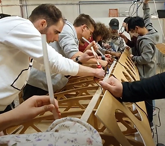
Once the ribs were glued to the spar the LE could be added. Gluing the LE to the wing assembly takes a significant amount of coordination. Hot glue must be applied to every rib along the length of the spar and have the LE bent over the ribs, all in about 30 second before the hot glue begins to harden. This was done by about 10 volunteers working in unison lead by William Crowther. The start of the process can be seen above.
The flaps and ailerons consist of only a single pre-cut piece that folds around all 3 sides to make the wedge shape and several internal ribs. It should take 2 volunteers less than half an hour to make a flap. These can be made relatively quickly and have far less complexity compared to the other wing assemblies.
-
Fuselage Assembly
The fuselage assembly came up short of the objective by only being able to assemble one of the sides of the fuselage over about a 2 ½ hour period. The shortcomings of the manufacturing process come mostly from having half the number of workers and half the expected amount of time to work. Despite this great progress was made and a lot was learned from observing and struggling through the build.
The manifesting method has been described in the training section and leaves a lot of the complication to the worker. The worker is fully responsible to make the tubes, cut the tubes to length, and make the complete angled joints of the system. This complexity causes many of the volunteers to hesitate to cut or glue something in fear of doing something irreversible. They also struggle to know where to start on the complex sub-assemblies when there is no clear starting point. The fuselage sections can be done in
any practical order, but some instruction could be added on where to start and what order the pieces could be added. Most of these problems could be mitigated by placing an experienced leader to point the team in the right direction and give the volunteers confidence.
Second Build Conclusions
Many of the goals set by the team were achieved but several potential problems appeared including:
-
Too much time spent during training.
-
After training, errors in parts and subassemblies created by the works were very low therefore too many spare parts were made.
-
Non-laser cut sections require the most experienced workers several hours to complete.
-
Inexperienced workers hesitate to perform a task that is irreversible and when given a task without a specific starting point. An example of this is when building the fuselage truss structure.
-
Large assemblies' teams struggle, therefore, create smaller sub assembly teams such as the spar, ribs, and leading edge flaps in place of a wing team.
-
Low performance of fuselage teams due to lack of team leadership.


Final Build:
Aim
-
Day 1: Test manufacturing methods and difficulty of manufacture of assemblies and subassemblies with the overall goal of completing the entire aerostructure over the course of a single day
-
Day 2: Fit non-structural systems of the aircraft
Objectives
-
Manufacture two main wing spars from cut sections
-
Manufacture two main wing sections (port and starboard)
-
Manufacture fuselage
-
Manufacture three tail sections (one was made prior to experiment)
-
Fit control systems, propulsion, and plywood hardpoints to the aircraft
Parts requirements
The number of unique parts has increased from the previous build. This is in part due to the addition of the tail section and from the pre-cut tail and wing spar. Some of the new parts come from the additional complexity of the rib slots and overlap joints. Several parts now have a left, right, and middle components, instead of one repeating component.
The required part count to build the aerostructure of the GFA is listed below in Table 6. The table helps to illustrate the scale of the GFA. The plane requires 170 20’’x 30’’ boards of foamboard and the aerostructure itself contains 570 individual pieces of foamboard. This number does not include the pieces to support the electronic systems of the aircraft or the plywood hardpoints and joints.
The total time spend using the laser cutter including time spend waiting, loading, un-loading, and post processing was about 10 hours.
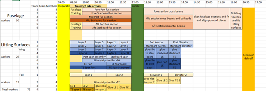
For this build day a schedule was made to help organise people into teams and to create deadlines for tasks. This schedule can be seen below with the planned schedule above and the actual order of events below. The schedule was made in an optimistic manner to encourage the volunteers to work quickly. This plan accounted for about 70 volunteers which was more than expected but the teams could operate in smaller groups.
The actual order of events has been estimated from the point of view and recollection of the build day leads David Gilstrap and William Crowther. This can be seen above in Figure 24. The actual events show a much more chaotic day then what was planned. The resultscan be summed up by a well-known quote by the Prussian general Helmuth von Moltke ‘’No plan survives first contact with the enemy’’. (Ratcliffe, 2016) The act of planning is most useful for setting up the day into realistic tasks and theorising how tasks will flow from one to another. This can also be better explained by another general, Dwight D, Eisenhower ‘’ In preparing for battle, I have always found that plans are useless but planning in indispensable.’’ (Boot Camp and Military Fitness Institute, 2022) The events of the day didn’t happen completely as planned for several reasons:
-
Lower attendance than expected and many late arrivals
Only about 50 % of the volunteers participated in the event with many arriving late as well. This made it difficult to have enough people to fill all the roles to get started at the beginning of the day. For this reason, progress was slow at the start of the day and several tasked were be pushed forward to later in the day.
-
Not enough leaders
The build day was planned to be split into 3 main group operating in 3 rooms at the start of the day. These groups being fuselage, wings, and tail sections. Only 2 build leaders were present on the day. This meant that it was problematic for a large group of volunteers to operate independently. The solution was to split the volunteers into 2 main groups working on complex assemblies of the aerostructure. A third smaller group was formed to work on more simple tasks with less supervision. The simple task given to the third group was to glue the strips to the ribs. This task was best suited for a less supervised group because it was relatively simple and needed to be repeated on many ribs prior to the assembly of the lifting structures. Having only 2 leaders present it would be difficult to manage any more than the present 40-45 volunteers. With this data available it can be suggested that for every leader present roughly 20 volunteers can be managed effectively.
-
No formal training session
By not having a formal training session the manufacturing could start immediately. The draw back being that the progress was slow and there was more mistakes and confusion at the start of the day. This was done because of concern of spending too much time
training like in the winter build. Overall, the not conducting a training session saved time but schedule was impacted and there was an increase in parts needing to be thrown out because of worker error.
Objective Evaluation
Main wing spar Assembly
The effort by the GFA team into redesigning the manufacturing process of the main spar helped to significantly reduced the effort required. The volunteers without significant experience were able to assemble both main wing spars in less time than took to make one during the winter build. This improvement allowed for the assembly of the wings to begin sooner.
Main wing assembly
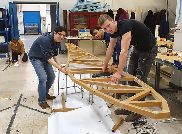
The main wing assembily had several manufactuing design improvments done including the overlap joints and the rib slot joints. The rib slot joints alowed the workers to work faster and more independently this can be seen above. Without the slots for the ribs, lining up the rear spar was a complex task and lots of measeuring and straighteing was required to ensure the mid ribs are placed on correctly.
Once the ribs are on, the task of bending and glueing the LE around the ribs is done in the same fassion as in the winter build. A significant amount of coordination is required to glue the LE to the ribs. The ribs need to be glued and held around the entire curve of the rib. In above can be 12 volunteers can be seen gluing the LE to the wing ribs. This picture is a still from a video of the process. In the video there are several specalised jobs including.
-
5 are glueing
-
2 are holding the wing steady
-
2 are holding the glue gun cables
-
1 are bending/bending the LE
-
1 is leading the operation (William Crowther)
The time taken for the group to glue the LE to the wing assembly is 75 seconds.
Fuselage Assembly
The fuselage is a different challenge to the rest if the plane it requires less coordination between workers but instead requires the workers to do their tasks independently. The Fuselage section didn’t receive any significant manufacturing process changes like other assemblies of the aerostructure. The entire fuselage is made up of Perrin tubes and about 100 tubes are needed to construct the fuselage. The laser cut Perrin tube blank sheet saves manufacturing time but it doesn’t make the manufacturing of the fuselage any simpler. This is due to the fuselage manufacturing process being less of an assembly of precut parts but instead every part needs to be custom cut by hand. Work on the fuselage begun at the start of the day with about 8-10 volunteers available. This was about a third of what was planned for. With less workers progress was slow.
The normal training of assembling the practice cross joint was skipped as about half of the volunteers had participated in the winter build. After the workers had demonstrated their proficiency in manufacturing Perrin tubes they were allowed to work more independently. The volunteers worked into a rhythm with most assembling the fuselage section while a few preferred to manufacture Perrin tubes full time. One worker manufacturing Perrin tubes can supply tubes to 2 workers assembling the fuselage frame. So, a work ratio of 1:2 is an appropriate balance. Progress on the 2D fuselage section was slow but steady. Progress on these sections will be proportional to the number of volunteers available as there is enough work and space for more workers. By lunchtime most of the 2D side sections were complete with the Mid section ready to be joined together.
Adding the cross members to the 2D sections was one of the only manufacturing techniques that had yet to be tested, so manufacturing methods and simple hands-on structural test were conducted during the construction process. The mid-section represented the most significant challenge. It contains more cross members then the other sections and contains structural bulkheads. This piece also houses the main wing and the undercarriage joints.
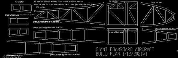
The general method for connecting the 2D sides to form the 3D fuselage section is to line up the sides on the printed template then cut and glue the crossmembers. The 3D sections are glued together to
form the entire fuselage. The template given to the workers on the day can be seen in below. Work on constructing the fuselage progressed steadily until the end of the day.
Tailplane sections Assembly
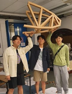
3 identical tailplane sections are needed for the GFA. One had been assembled previously about a week before the build day by volunteers at the University flight test course lead by William Crowther. Using this pre-build tailplane for the GFA, only 2 additional tailplane sections were required to be assembled.
The original plan for the tail sections was to complete them early in the day. In actuality the tail sections were pushed to the end of the day. With just the ribs being prepped at the start of the day. The decision to do this came from mostly the lack of available leadership to supervise their construction but instead waited until the more complex larger assemblies were complete. The manufacturing process for the tail
sections are nearly identical to the main wings but with the benefit of being much smaller. A small group of 2-3 volunteers. Could assemble the tails planes in a few hours. Using the experience of assembling the main wing section volunteers were able to assemble the tail sections without significant problems.
Easter Build Day 2: Systems
The second build day consisted of just a handful of volunteers working from about 9:30 to 17:00. About 4-5 volunteers participated. More volunteers asked to come to the event, but the GFA team turned them down not expecting there to be much work for the volunteers to do. Because of our efforts to reduce the numbers of volunteers too few arrived for the day.
The GFA team and other volunteers managed to fit the plane with the electrical systems, mount the plywood wing and tail joints, and set up many of the control surfaces.
Control systems
For the control systems of the aircraft. It was needed to attach supporting foamboard on the ribs where the servos will be mounted and attach plywood plates for the servo bolts. Foamboard is a weak material and would give little resistance for the bolts. This proved to be a more difficult task then expected. New servo plates needed to be laser cut for both the servos and servo horns and custom foamboard pieces need to be cut to support the ribs. Servo push rods needed to be measured, cut, and set. Doing these unexpectedly complex tasks took up a large portion of the day. These issues could have been avoided if better care was taken into testing the manufacturing process beforehand. A possible solution for avoiding tinkering with small nuts and bolts would be to just hot glue the servos in place. News servo push rods also are ordered that ease the manufacturing process.
Mounting Plywood joints
Jointing the plywood wing and tailplane joints was done by utilising smart phone levelling app to square the fuselage, wing, and tailplane. The tail section of the fuselage was assembled with a slight twist this was solved by setting the tailplane joint in the correct position and filling the gaps with foamboard above and below to ensure a tight fit. A similar process was done to the main wing joint. The nose motor mount not mounted because the team was unsure of the design thrust vector.
Electronics systems
The wiring of the system was done by a set of volunteers after a short training on crimping and cutting wires. The volunteers were able to measure, cut and set most of the wires for the plane. The other task regarding the electrical systems are too complex and need a experienced person to assemble reliably and safely. A PhD student who handled the purchasing and organisation of the electrical systems handled the installation of the communication, telemetry, and guidance systems.
Final Build Conclusions
Overall, this day was less successful than the previous day. Many of the tasks for the day were underestimated. Important lessons were learned. Such as the importance of planning and testing out manufacturing processes before all the resources come together. A few useful changes would be.
-
Testing manufacturing processes before hand
-
Having all (laser cut) parts ready for the build instead of fabricating them on the day
-
Have easy access to all necessary geometry (i.e., tail set angles and thrust vectors)


The teams being led by Dr William Crowther were able to experiment and make a few mistakes during the manufacturing process. Several layers were thrown out due to worker error. This did not affect the final products as sufficient spare parts were available. The method used to construct the spar previously was to start gluing the inner 6 layers of the spar together and then attach the 2 outer layers. It was too difficult to match set geometry of the spar this way. So instead, the layers were glued together staring with the outside layers. By working this way, the two halves of the spar could be manufactured in parallel with one group gluing together layers 1-4 and another gluing together 5-8. An image can be seen of the volunteers combining the 2 halves of a main wing spar can be seen to the left. Several extra layers were made by mistake due to poor communication. The better constructed layers were used in the final product with the rejects being thrown out.